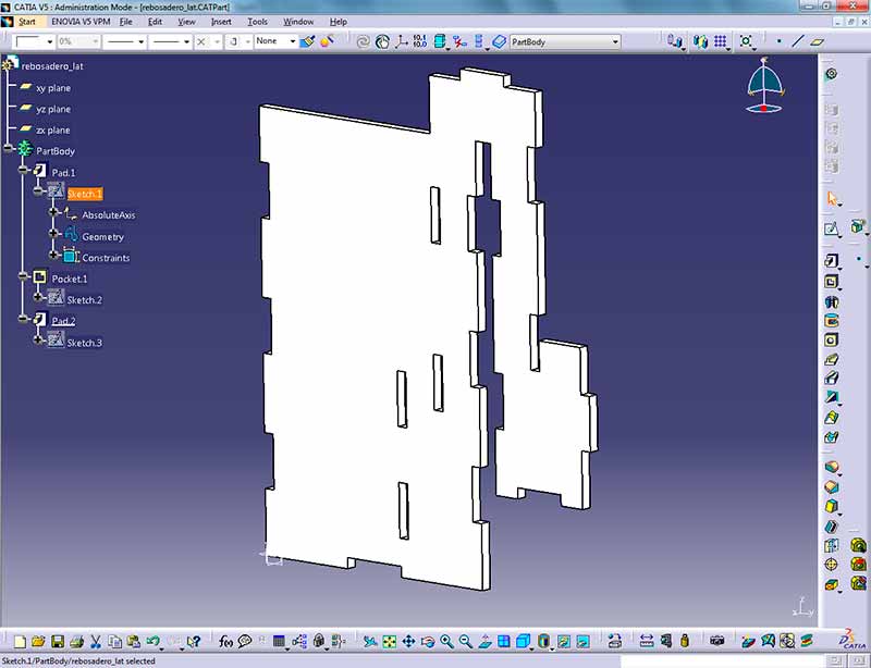
Catia Project 3d Elements
Projecting 3d elements onto the view plane.
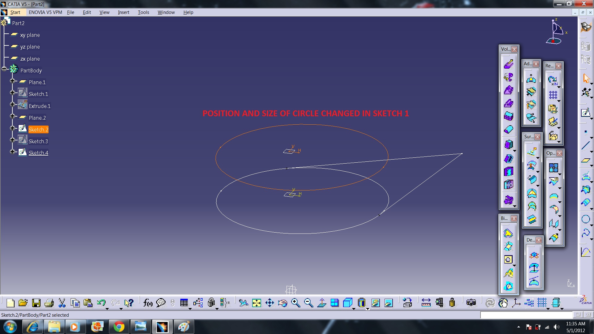
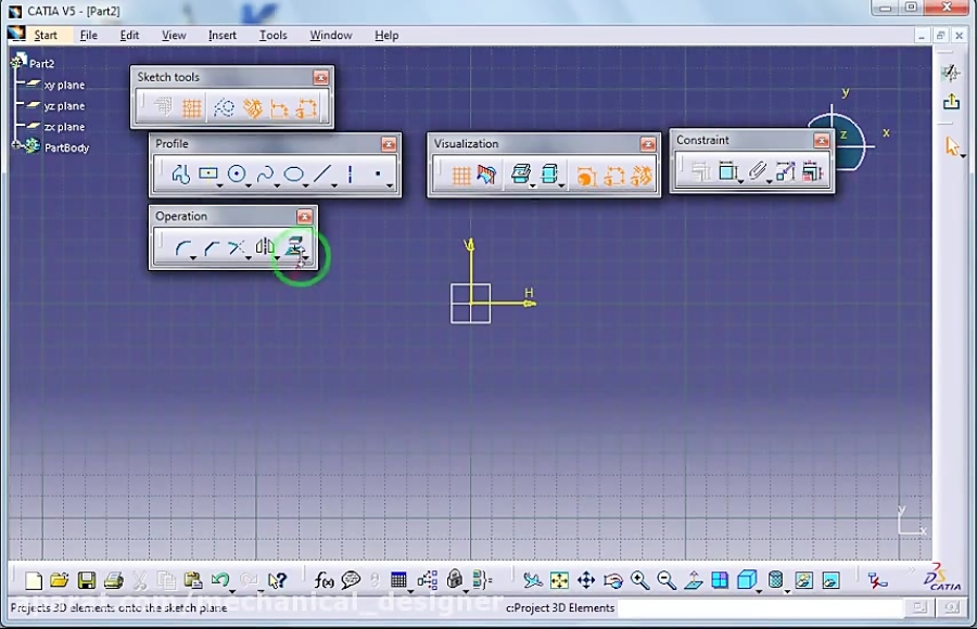
Catia project 3d elements. Double click the left view to activate it. To move them first use the isolate command. Click anywhere on the screen outside the geometry. In the sketcher window click on project 3d elements 5.
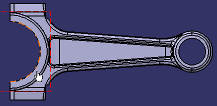
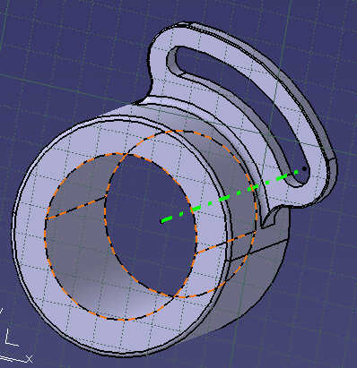
Open a catpart containing 2d sketch elements projected in 3. Select the project 3d elementsicon then select the face of the part. A sketch element which contains point line and a curve is not selected. This task shows how to project edges elements you select from the 3d area onto the sketch plane.
2dlayout for 3d design. Then click on create datum icon 6. Click project 3d elements. The edges are projected onto the sketch plane.
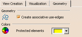
Select the project 3d elements. These projections are yellow. Multi select the edges you wish to project onto the sketch plane. Multi select the edges you wish to project onto the sketch plane.
These projections are yellow. The edges are projected onto the sketch plane. You can apply the relimitation corner and chamfer commands on projections. Click on the sketcher icon and select xy plane in the spec tree 4.
Click project 3d elements in the 3d geometry toolbar or select insert 3d geometry use edges project 3d elements from the menu bar. Switch to 2dlayout for 3d design workbench. Start catia v5r16sp4 hf61 2. Select the geometry using a trap box all selected elements get highlighted 7.
Open partigs in catia 3. Select the element to be projected. Imec and mentor a siemens business collaborated to identify potentially less obvious process and design limitations and trade offs between the three samp techniques. Select the all sketch elements by dragging and dropping.
It may be hidden in the bottom right corner. You cannot move these elements. This icon is located in the operationstoolbar near the bottom of the right side toolbar area.


